

Introduction
Climate change is an eminent global issue driving the world to transform both its energy generation and consumption to achieve the goal of net zero Green House Gas (GHG) or Carbon emissions within the next 20 – 40 years[1],[2].


(a) Global GHG emissions by Gas (b) Global GHG emissions by Sector
Figure 1: Source: epa.gov
The Figures above are extracted from the Intergovernmental Panel on Climate Change (IPCC) Fifth Assessment Report (AR5) in 2014. According to this report, in 2010 Carbon Dioxide (CO2) emissions mostly came from fossil fuel combustion and industrial processes, and Methane (CH4) emissions came from agriculture, the production and transport of fossil fuels and the decay of organic waste in landfills.
It can be then deduced from both Figures that Electricity Production, Agriculture, Industry and Buildings account for a total of 76% of Global Green House Gases, 92% of which being CO2 and CH4 as shown in Figure 2.

Figure 2: An Illustration of some of the main sectors contributing to the Global GHG emissions
Now that this point has been made, let’s explore Combined Cooling Heating and Power (CCHP) Systems, its integration with renewable energy resources in a Microgrid setup, and its benefits to energy production, consumption and the environment, then get back to this particular point and make the necessary connections to conclude.
The Concept of CCHP Microgrid

Figure 3: Combined Cooling Heating and Power Microgrid Process Flow
CCHP or Trigeneration Systems are simply represented in Figure 3. The Combined Heat and Power (CHP) unit Prime Mover (Reciprocating Engine, Fuel Cell, Turbine, … etc.) primarily designed to produce electricity from burning Gas (Natural Gas, Biogas, Hydrogen … etc.), also produces hot water, or steam. This happens by extracting waste heat from the unit using water as a medium for heat transfer.
The water temperature rises as a result and is then circulated into a piping system to be used either directly for heating processes, or indirectly for cooling processes. In a cooling process specifically, the hot water is fed into an Absorption Chiller, which is a type of chiller that converts heat energy into chilled water.
The Main Benefits CCHP Microgrid
The primary benefit of CCHP systems can be easily spotted from Figure 3, which is its much higher efficiency than the traditional energy supply setup (Utility Electricity, Boilers and Electric Chillers). Figure 3 clearly shows a single fuel source producing several forms of energy on-site, which eliminates many of the undesirable issues of Utility long distance power transmission, high emissions and outages.
The CCHP system continuously generates Electricity, Cooling and Heating and eliminates the need for backup power generators and their low efficiency and high emissions. This in turn has a dramatic effect on lowering emission levels, energy costs and increasing energy reliability and resilience.
The Future Energy Demand Gap

Figure 4: Source: World Bank Group Figure 5: BESS use case and the load demand gap
When thinking about a carbon neutral future, Renewable energy is the first thought that comes to mind and any technology that uses fossil fuel as the primary source of energy is immediately frowned upon. But the fact is, Solar, wind, Hydro … etc. technologies cannot by themselves be the sole source of energy generation for every region of the world due to limitations on their availability and the space to deploy them.
Take the North East of North America for example, where there is a very high demand for heating during the winter season with low Solar energy potential (see Figure 5), even with aid of Batteries to store excess solar generation and discharge for a few of hours later, there’s still an energy gap that needs to be filled for the rest of the day and that’s only for the electric load (see Figure 5).
CCHP systems have great load following and power quality capabilities which make them a great anchor in a Microgrid setup (Source for Frequency and Voltage Regulation) when the Microgrid switches to island mode during Grid power outages (more on that later).
The Natural Gas Transition
One might think, even if the efficiency is much higher than the grid, there’s still a level of CO2 emission from the combustion process and CH4 emission from Natural Gas production and transportation which hinders the progress to the carbon neutral end goal.
But that risk can be mitigated by transitioning from Natural Gas to other renewable gases such as (1) Renewable Natural Gas (RNG), (2) Biogas[3], or (3) Hydrogen. Investing in RNG and Biogas have the ability to capture both the CO2 and CH4 emissions from Livestock, Manure, Dairies, Landfills, Wastewater treatment plants and Landfill-diversion facilities. This is accomplished by storing their waste in anaerobic lagoons or digesters to maximize methane production and then capturing the methane to use as an energy substitute.
According to So-Cal Gas:
RNG is considered a carbon-neutral fuel because it comes from organic sources that once absorbed carbon dioxide from the atmosphere during photosynthesis. RNG has even greater benefits when it’s produced from organic waste that would otherwise decay and create methane emissions. By capturing more greenhouses gases than it emits, this RNG is actually considered carbon-negative!” [4]
There are currently 130 Operational / Online, 37 Under Construction,73 In Substantial Development RNG production facilities in North America (Figure 6)[6].

Figure 6: Source: rngcoalition.com
In addition to RNG and Biogas, many CHP prime mover manufacturers (primarily Fuel Cells) are now providing retrofit transitioning solutions for their CHP products from Natural gas to Hydrogen by using a blend of both gases up to 100% Hydrogen once the time comes when Hydrogen production has matured enough. The Hydrogen Journal published a map showing Hydrogen projects around the world which provides some insight on the progress of the technology[7], which still has ways to go as opposed to the current status of RNG adoption.
The Full-Blown CCHP Microgrid Solution
At this point you might be thinking “Ok, fine, tell me more about CHP or CCHP systems, how would they support a carbon neutral future?”.
Well, as an example, when you combine CCHP with Solar Photovoltaic (PV) array and Battery Energy Storage System and tie all this into the Grid in a carefully controlled and optimized system, you’ve got what is called a Grid-tied Microgrid (Figure 7 & Figure 8). Such Microgrid will generate on site continuous high efficiency and low to negative emission (if RNG is used) electricity, heating and cooling that displaces low efficiency Utility produced electricity and low efficiency onsite Cooling and Heating Equipment.
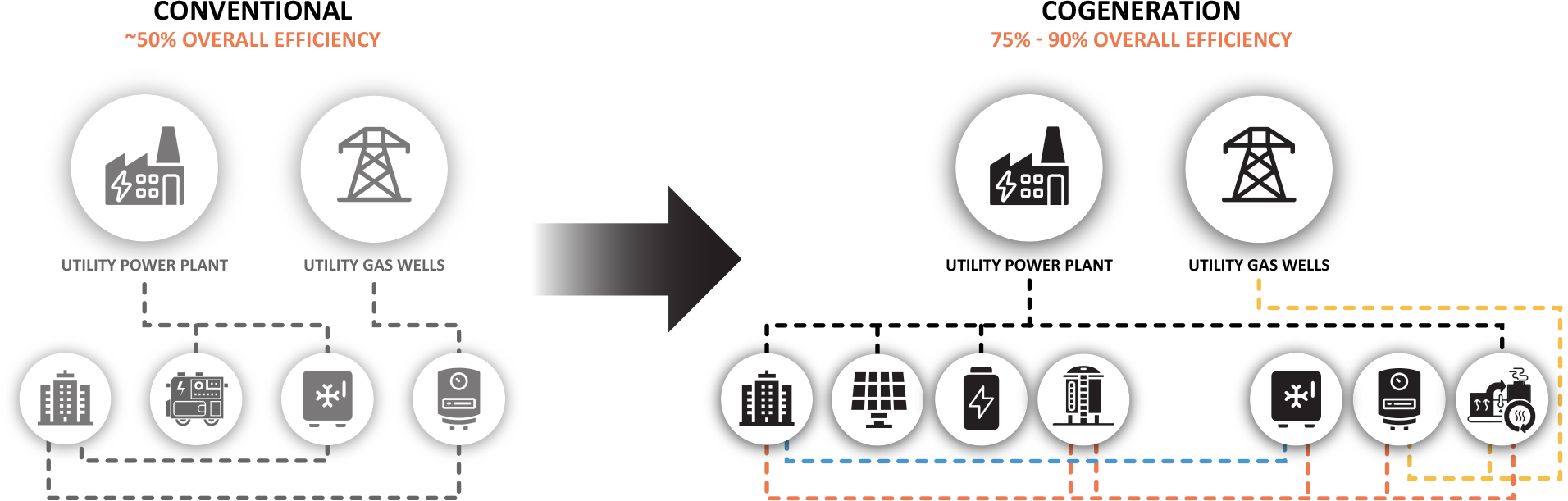
Figure 7: Traditional VS Microgrid Energy supply Setup

(a) Grid-Tied Generation Distribution (b) Island Mode Generation Distribution
Figure 8: Example of Grid-Tied VS Islanded Microgrid Electric Energy Distribution over a day
Figure 7 & Figure 8 show a simplified representation of a traditional Energy setup as opposed to an Advanced Smart Microgrid for most small to mid-sized buildings or industrial process facilities. As complicated as it may seem, I’ll try explaining it as best as I can. It is important to understand the dynamics of the interaction of the different on-site energy resources to value the significant benefits of it.
Figure 7 shows on the left side of the large arrow a Traditional Energy setup (in grey color) where 100% of the Electricity and Cooling demand are met by the Grid, and 100% of Heating is met by onsite boilers fed with Natural Gas with an Oil fueled backup generator in the case of a power outage, no further explanation there.
On the right side of the arrow is a full blown CCHP microgrid setup where:
- Up to 100% of Utility electricity can be displaced with (a) PV, (b) CHP Unit and (c) BESS.
- Up to 100% of Boiler Heating can be displaced with (a) CHP Unit, (b) Standby Boiler and (c) Thermal Energy Storage (TES).
- Up to 100% of Electric Chiller Cooling can be displaced with (a) Absorption Chiller and (b) TES.
Now this seems like a lot of equipment, but all these equipment do not need to exist in every CCHP Microgrid project. At minimum, the CHP Unit with Solar PV and Battery Storage system optimized and coordinated through an advanced control system need to exist in order to call it a Microgrid.
When working with CCHP projects, running the prime mover as many hours as possible will provide the highest return on investment. Many States that provide incentives for CHP projects require the unit to run at least 5000 hours a year (a typical year has 8760 hours). When working with CCHP projects, the hours utilization become even greater because the CHP unit continues running during the summertime to serve the cooling demand which makes the unit run all year long. Adding TES makes sure any excess hot and/or chilled water is stored and used later at peak demand. Utilizing thermal storage will depend on the economic viability of it.
In Figure 5, there was an electric load demand gap that was described before in a typical PV-BESS Microgrid setup. This demand will typically be served by lower efficiency, quality and reliability grid power. Figure 8 shows how this gap can be filled with high efficiency, quality, reliability and resiliency CCHP Microgrid system.
Figure 5 & Figure 8 both represent the same exact electric load and PV production profiles (energy over time), but the difference is, how the energy gap in Figure 5 is filled as shown in Figure 8. To explain it further, the blue line/area represents the load profile and the yellow line/area represents the PV production profile (a line represents power and an area represents power times time, which is energy).
The yellow area in Figure 5 represents the excess PV energy that is stored in the BESS and later discharged when needed, which is represented as the green area. The demand gap in Figure 5 is represented in Figure 8 as the red area which is the amount of energy that the CHP unit fills.
Figure 8 (a) shows an example of how the electric load might be met at normal grid-tied operation using the different energy resources. At times of the day when there’s excess generation from either the PV array or the CHP it’s optimally utilized to either sell it back into the Grid or to charge the BESS, which is shown as any areas below the x-axis (Time of Day axis) in the figure.
This healthy Bidirectional flow of electricity to and from the Grid will drive:
- the increase in Grid capacity when future demand increases,
- lower energy costs from selling electricity to the Grid Market and
- upgrade of aging Grid infrastructure to accommodate the decentralized increase in capacity and better response to outages, leading to higher reliability and resilience of both the Grid and end user.
Figure 8 (b) on the other hand shows an example of how load can still be met during power outages when the advanced microgrid control system reorganizes, optimizes and control the energy resources to self-sufficiently serve the load without any loss of power.
Conclusion
CCHP evidently has a pivotal role in a Net Zero Carbon Future even if we have to start using the existing Natural Gas supply system, then transition to renewable gases later. The sun isn’t always shining and the wind isn’t blowing everywhere in the world. CCHP systems are an essential part of the equation.
CHP is a very mature technology, especially Reciprocating Internal Combustion Engines (RICE) run by natural gas, there are plenty of manufacturers to choose from with sizes from 5kW all the way to 10 MW. The potential for new projects is tremendous. To give an example, there is currently over 82 GW of CHP capacity installed in the United States, and potential for 240+ GW more in a country that has just over 1,000 GW of current electric generating capacity.
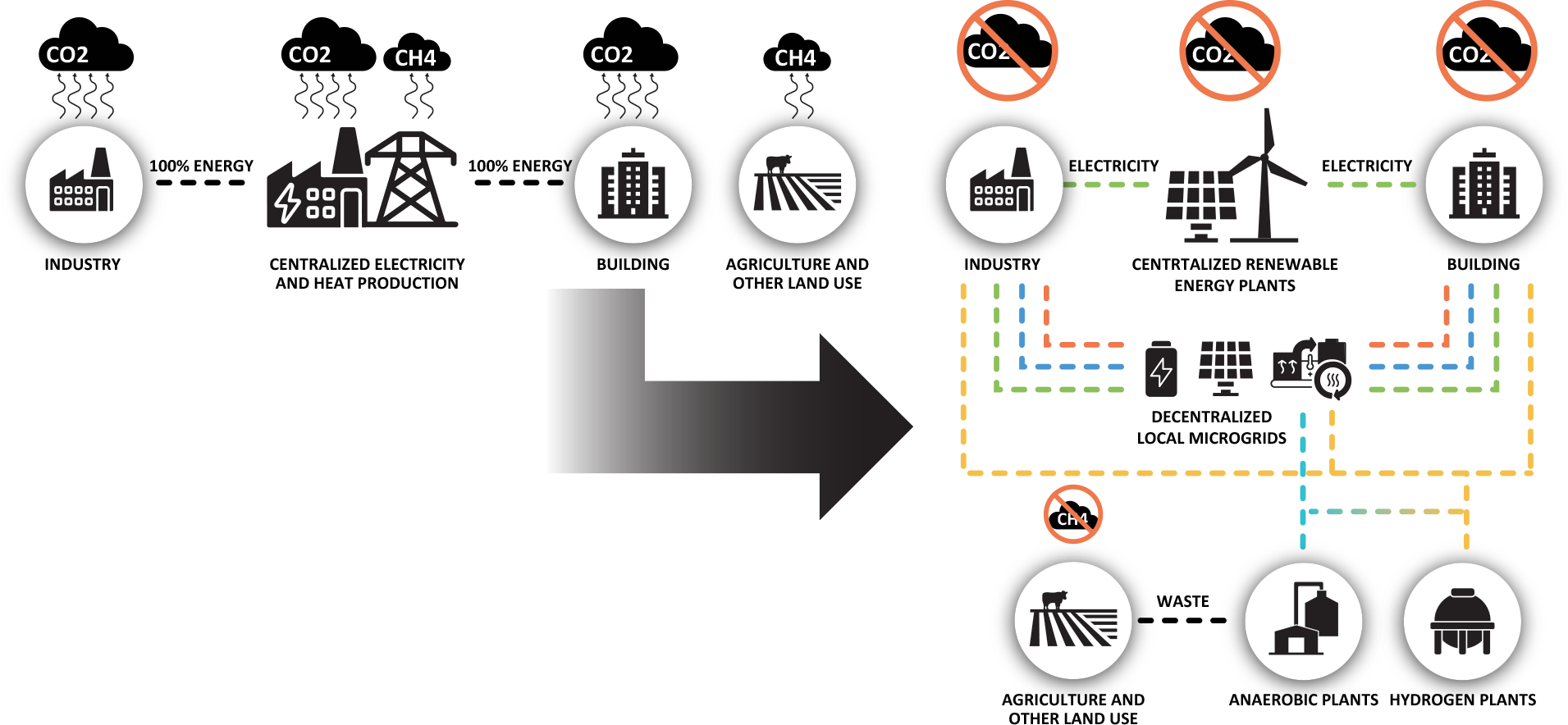
Figure 9: What a Net Zero Carbon Future can look like
Now circling back to the statement made in the introduction, and the illustration made in Figure 2 , I’d like to end this report with a really nice picture of how that can change in 2040 – 2060, with the illustration in Figure 9. CH4 emissions from organic waste, disposed by Agriculture and other land use sector, are removed, turned into pipeline quality RNG through anaerobic processes, pumped into existing Natural Gas Pipeline, and distributed to the Buildings and Industry sectors.
Blending Hydrogen with RNG, or using separate Hydrogen pipeline is also on the lookout. CO2 emissions from Centralized Electricity and Production plants are eliminated by replacing them with Renewable Energy plants, like Utility scale Solar and Off-Shore Wind farms, and Decentralized local or community microgrids, with CCHP systems being a major part of it.
Microgrids are the future of energy, and CCHP systems are a big part of it. Checkout our Design Software for Cogeneration/Combined Heat and Power (CHP) Microgrids; CogenS™ your ultimate tool for modeling, simulation and optimization.
[1] Hydrogen projects around the world by The Hydrogen Journal
[5] https://www.rngcoalition.com